Files:
Background:
So now that you are out and about writing your own code for your ARM chip the need to use interrupts will inevitably arise. Interrupts are great for handling “side jobs” while a main task is being executed. If you are unfamiliar with the concept of interrupts then refresh your memory. Interrupts on the ARM work the same like many other microcontrollers. It’s just setting them up that’s the tricky part. 😉 Remember to refer to your lpc-2148 manual for full details.
Interrupts:
An interrupt can be configured to be set off by a variety of triggers. Most common are external interrupts (i.e., the chip awaits a signal change on a pin connected to a sensor or switch) and timed interrupts. Interrupts triggered by the microcontroller’s timer are really handy for when you periodically want to handle “house keeping” tasks or data logging. In this lab we will be focusing on external interrupts.
Board Setup:
We will be using pin P0.14 as the external interrupt pin. We must configure the microcontroller appropriately. Note that the Olimex LPC-2148 board does not explicitly label pin P0.14. On this board it is labeled “BSL”.
Steps to setting up an external interrupt:
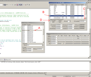
1. First modify the PINSEL0 register to change the function of pin P0.14 from general purpose IO (GPIO) to external interrupt 1 (EINT1). I trust you can look up, and modify the correct bit fields for this. Fig 1-A.
2. Now we must modify the Vector control 0 register (VICVectCntl0). There are 16 of these registers (VICVectCntl0 to VICVectCntl15), each controlling a vectored IRQ slot. VICVectCntl0 has the highest priority, while VICVectCntl15 has the lowest priority.
Let’s modify VICVectCntl0; Bit fields 4:0 is for the number of the interrupt request. External Interrupt 1 (EINT1) is Channel 15 (Fig 1-B). We want this interrupt channel to be assigned to IRQ slot 0 (highest priority). So we must modify register VICVectCntl0 to allow this. We load bit fields 4:0 of VICVectCntl0 with Hex:0x0F because we want channel 15 (Hex:0x0F) in this IRQ slot. Bit field 5 of VICVectCntl0, is for IRQ slot enabled. When this bit field is 1, this vectored IRQ slot is enabled. THIS IS NOT THE SAME AS ENABLING AN INTERRUPT, this is just to enable the vectored IRQ slot!!! Disabling a vectored IRQ slot in a VICVectCntlX register does not disable the interrupt; it just changes the interrupt from vectored to non-vectored form.
3. Time to modify the Vector Address 0 register (VICVectAddr0). This register holds the address of the Interrupt Service Routine (ISR). This is where you tell the microcontroller the program function you want executed when an external interrupt is triggered. I named my external ISR “EXTINTVectoredIRQ”. The following line of code extracts the memory location of that function and stores it in VICVectAddr0.
     //pass the address of the IRQ into the VIC slot
     VICVectAddr0 = (unsigned)EXTINTVectoredIRQ;
On my particular set up, the function was stored at location 0x00000280, so that’s the value that was loaded in. Fig 1-C. Note: the “__irq” keyword tells the compiler that the function is an interrupt routine. You may have to tweak this depending if you are using the CARM or RealView compiler within Keil.
4. Finally, it’s time to actually enable the external interrupt. We will now modify the Interrupt Enable register (VICIntEnable). This register controls which of the 32 interrupt requests and software interrupts contribute to FIQ or IRQ. We only care about the external interrupt, which is bit field 15 of this register. We set this bit high to enable the external interrupt.
Explanation of Code:
The “main” task of this code is to simply blink the LEDs. If the “main” task is interrupted, execution goes into the ISR. The ISR has code that will produce a beep sound via the buzzer mounted on the LPC2148 board. You will need to wire a jumper cable from pin P0.14 to ground in order to trigger the interrupt. While the pin is tied to ground the buzzer will keep beeping. Notice that you can interrupt the main code at different points within the LED toggle cycle. You might interrupt it during an ON cycle, or you might interrupt it during an OFF cycle.
Above and Beyond:
I didn’t cover that there are different kinds of level triggering configurations of the external interrupt. Maybe you don’t want an active low/high level sensitive interrupt but perhaps a falling/rising edge interrupt trigger. Well all that is possible with the right configuration. Have fun further researching that and the various other types of interrupts the ARM can handle.
Have fun!
Video Demo:
Code – main.c :
/******************************************************************************/
/* Name:            Juan Gutierrez                                            */
/* URL:             www.armjunkie.com                                         */
/* Date:            10/10/2008                                                */
/* Project #:                                                                 */
/* Project:                                                                   */
/* Filename:        main.c                                                    */
/* Language:        Embedded C                                                */
/* Keil Version:    uVision 3 V3.50                                           */
/* Target Board:    Olimex LPC-P2148                                          */
/* Osc Freq:        12.000 Mhz                                                */
/******************************************************************************/
#include <LPC21xx.H>
#include "debug_tools.h"

void EXTINTVectoredIRQ (void)__irq;

int main (void)
{
     int i, k;
     //Set the LED pins as outputs
     IODIR0 = 0x00000C00;
     //Turn OFF the LED pins
     IOSET0 = 0x00000C00;

     //Set P0.14 to EINT1
     PINSEL0 = 0x20000000;

     /*NOTE:
          VICVectCntl0
          ----------------------------------------------------------------------
          Vector control 0 register. Vector Control Registers 0-15 each control
          one of the 16 vectored IRQ slots. Slot 0 has the highest priority and
          slot 15 the lowest.

          Refer to page 57, Table 52 of UM10139 PDF for details
     */
     //select a priority slot for a given interrupt
     VICVectCntl0 = 0x0000002F;

     /*Note:
          Vector Address registers 0-15 (VICVectAddr0-15 - 0xFFFF F100-13C)
          ----------------------------------------------------------------------
          These are a read/write accessible registers. These registers hold the
          addresses of the Interrupt Service routines (ISRs) for the 16 vectored
          IRQ slots.
     */
     //pass the address of the IRQ into the VIC slot
     VICVectAddr0 = (unsigned)EXTINTVectoredIRQ;

     /*Note:
          Interrupt Enable register (VICIntEnable - 0xFFFF F010)
          ----------------------------------------------------------------------
          When this register is read, 1s indicate interrupt requests or software
          interrupts that are enabled to contribute to FIQ or IRQ. When this
          register is written, ones enable interrupt requests or software
          interrupts to contribute to FIQ or IRQ, zeroes have no effect.
     */
     //enable interrupt
     VICIntEnable = 0x00008000;
     while(1)
     {
          //Blink LEDs,
          //While P0.14 is brought low an interrupt will occur. In the ISR
          //the buzzer will BEEP. To Exit ISR, bring P0.14 high again.
          for (i = 0; i < 500000; i++ );
               //Turn OFF the LED pins
               IOSET0 = 0x00000C00;
          for (k = 0; k < 500000; k++ );
               //Set the LED pins
               IOCLR0 |= 0x00000C00;
     }
}

void EXTINTVectoredIRQ (void)  __irq
{

     //Beep
     beep(1);

     /*NOTE:
          EINT1
          -----------------------------------------------------------------
          In level-sensitive mode, this bit is set if the EINT1 function is
          selected for its pin, and the pin is in its active state. In
          edge-sensitive mode, this bit is set if the EINT1 function is
          selected for its pin, and the selected edge occurs on the pin.
     */
     //Clear the peripheral interrupt flag
     EXTINT = 0x00000002;

     //Dummy write to signal end of interrupt
     VICVectAddr = 0x00000000;
}
Code – debug_tools.h :
#ifndef __DEBUG_TOOLS_H
#define __DEBUG_TOOLS_H

//Makes the buzzer BEEP for debugging
//Argument 'a' is the number of beeps to perform
void beep(int a);
#endif  // __DEBUG_TOOLS_H
Code – debug_tools.c :
#include "debug_tools.h"
#include "LPC21xx.h"

void beep(int a)
{
	int		i,j,k,l;

     //set pin connected to buzzer as output
     IODIR0 |= 0x00003000;	// P0.12, P0.13 output
     IOSET0 =  0x00003000;   // Set high
	for(l=0;l<a;l++){
		for (i = 0; i < 250000; i++ );
		for(j=0;j<100;j++){
			for (i = 0; i < 2400; i++ );
			IOSET0 |= 0x00002000;
			for (k = 0; k < 2400; k++ );
			IOCLR0 |= 0x00003000;
		}
	}
}

